


We have been building battery chargers in Delhi since 1994, which means we have built every generation of this technology and repaired the ones that came before. The change over that period is not a story about incremental improvement. It is a story about three fairly distinct architectures, each of which made the previous one obsolete for reasons an owner can actually feel.
This is worth understanding because all three are still on sale. Walk through any market that serves e-rickshaw drivers and you will find 1990s technology sitting next to current technology at a third of the price, and nothing on either box explains the difference.
Generation one: the iron transformer
The original approach is about as simple as electrical engineering gets. Mains AC goes into a heavy iron-cored transformer that steps the voltage down, through a rectifier that turns AC into DC, through some smoothing, and out to the battery.
Its virtues are real. There is almost nothing to fail. Any workshop in the country can repair one with a soldering iron. It tolerates the kind of mains abuse — spikes, sags, brownouts — that would destroy more sophisticated electronics. And it is cheap, because a transformer is just wire and iron.
Its problems are equally real, and they are all consequences of the same physical fact: a transformer operating at mains frequency, 50 Hz, must be physically large to handle a given power.
| Problem | Cause | What the owner notices |
|---|---|---|
| Efficiency of 70–80% | Core losses, copper losses, rectifier drop | A fifth to a quarter of the electricity becomes heat |
| Weight of 8–15 kg | Iron core mass scales with power at 50 Hz | Nobody carries it anywhere |
| Output follows the mains | No regulation — output is a fixed ratio of input | Charging behaviour changes with supply voltage |
| Crude termination | Timer, or a simple voltage threshold | Over- or under-charging, both harmful |
| Runs hot | All those losses appear as heat | Shortened life for the charger and anything near it |
The third row is the one that matters most in India and is almost never discussed. A transformer charger’s output is a fixed ratio of its input. If your supply sags to 190 V during the evening peak — entirely normal in much of the country — the charger’s output sags by the same proportion, and it simply cannot finish the job. If the supply swings high at 2 am, the output goes high with it, and the battery is over-charged.
For lead-acid this is tolerable, because lead-acid gasses off a modest overcharge and carries on. For lithium it is not tolerable at all, and this is the fundamental reason the transformer architecture could not survive the transition to lithium packs.
Generation two: switch-mode
The switch-mode power supply solves the size problem with a trick that seems like cheating: rather than transforming at 50 Hz, rectify the mains to DC first, chop it into a high-frequency square wave at tens of kilohertz, and transform that.
The physics that makes this worthwhile is that the required size of a transformer core falls as frequency rises. Move from 50 Hz to 50 kHz — a factor of a thousand — and the magnetic component shrinks dramatically. An SMPS charger that outperforms a 12 kg transformer unit weighs perhaps 1.5 kg.
But the size reduction, striking as it is, is not the important part. The important part is that switching is controlled. A feedback loop measures the output and adjusts the switching duty cycle thousands of times a second to hold that output exactly where it should be.
Once output is under active control rather than being a fixed ratio of input, the charger can hold a precise voltage regardless of what the mains is doing, and it can deliberately move between a constant-current phase and a constant-voltage phase. Both are prerequisites for charging lithium safely. The transformer architecture could not do either.
Efficiency improves at the same time, typically to 88–93%. That is not a marginal gain. Charging a 5 kWh pack daily, the difference between 75% and 90% efficiency is about 1.1 kWh a day — roughly ₹2,600 a year at ₹8 a unit. A better charger repays its price difference within a year on electricity alone, before considering what tight voltage regulation is worth to the battery.
The two-phase charge, and why the last hour takes so long
Controlled switching made a proper charging profile possible, and it is worth understanding because it explains a question every owner asks.
Constant current. The charger delivers its full rated amps. Pack voltage climbs steadily. This phase does the bulk of the work, taking the pack to roughly 80–90%.
Constant voltage. When the pack reaches the target voltage — 58.4 V for a 16-cell LFP pack, 69.4 V for a 19-cell one — the charger stops pushing more current and instead holds that voltage steady. Current falls away on its own as the pack fills.
That taper is why the last stretch of a charge takes 45 to 60 minutes almost regardless of how large your charger is. Doubling the charger’s current halves the first phase and barely touches the second.
It also does something invisible and important: cell balancing happens during the taper. The BMS bleeds charge off cells that reach full early so the others can catch up, and it can only do that while the pack is being held at the top of its range. An owner who unplugs as soon as the current starts falling is preventing the BMS from doing its job, and over months that costs real capacity. We cover this in the charging habits guide, where it is the single most commonly missed piece of maintenance.
Generation three: the charger that knows something
SMPS gave us control. The current generation adds a microcontroller and, with it, judgement.
| Capability | What it does | Why it matters |
|---|---|---|
| Multi-stage profiles | Different behaviour for a deeply discharged pack versus a top-up | Gentler on cells that need gentleness |
| Temperature compensation | Adjusts or halts based on pack or ambient temperature | Prevents charging a hot or freezing pack |
| Chemistry selection | Correct profile for LFP versus lead-acid | One unit can serve a mixed fleet safely |
| BMS communication | Charger and pack exchange state | The pack can ask the charger to stop or slow down |
| Fault diagnosis | Distinguishes a bad pack from a bad supply | Stops good chargers being replaced for battery faults |
| Charge-level indication | Shows genuine progress | The operator can plan around it |
The temperature row deserves emphasis in an Indian context, in both directions. Charging a pack that is already at 50 °C after a hard day compounds thermal stress at the worst possible moment, and heat is the dominant driver of battery ageing. Charging a pack that is below 0 °C — entirely possible on a January morning in Delhi, Punjab or Haryana — plates metallic lithium onto the anode and causes permanent, cumulative damage.
Our 58V and 69V lithium chargers are SMPS-based with charge-level indicators on the case, so the operator sees genuine progress rather than guessing from a single lamp.
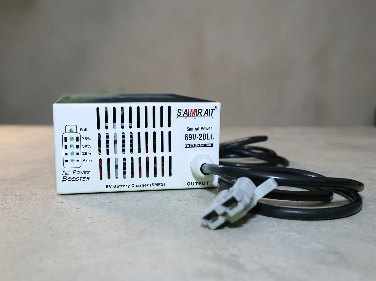
69V · 22A Lithium EV Charger
SMPS control with proper constant-current and constant-voltage phases, so the taper finishes and the BMS can balance. For 19S LFP packs.
₹5,460 incl. GST · 12-month warranty
What “fast charging” actually means, and where it stops
Every generation of charger has been sold partly on speed, and the claims deserve unpacking because the limits are not in the charger at all.
Charging current is properly expressed as a C-rate — current divided by pack capacity in amp-hours. A 25 A charger on a 100 Ah pack is 0.25C. The same charger on a 50 Ah pack is 0.5C. The charger has not changed; the stress on the cells has doubled.
| Charger | C-rate | Constant-current phase | Plus taper | Total |
|---|---|---|---|---|
| 10 A | 0.1C | ~9 hours | ~1 hour | ~10 hours |
| 25 A | 0.25C | ~3.6 hours | ~1 hour | ~4.6 hours |
| 50 A | 0.5C | ~1.8 hours | ~1 hour | ~2.8 hours |
| 100 A | 1C | ~0.9 hours | ~1 hour | ~1.9 hours |
Read the last two columns together and the diminishing return is obvious. Going from 25 A to 50 A halves the first phase but leaves the taper untouched, so total time falls by only about 40%. Doubling again to 100 A buys another 30%, at four times the original current and a great deal more heat.
The binding constraint is not the charger’s capability. It is three things the charger cannot change: what C-rate the cells are rated to accept, what the BMS will pass on its charge side, and how much heat the pack can shed while it happens. Exceed any of them and the BMS trips, or worse, it does not.
This is why we size traction chargers between 0.2C and 0.3C as a default. It fills a pack inside an overnight window or a long break without the thermal penalty, and it sits in the range where LFP cycle life is at its best. Anyone selling you a much larger charger for the same pack should be able to explain what in the pack is rated to accept it.
Telling the generations apart on a market stall
Nothing on the box will say “transformer”. Four checks will tell you anyway.
- Pick it up. The single most reliable test. Anything over about 5 kg for a 1–2 kW charger has an iron transformer inside it. A comparable SMPS unit is 1–2 kg.
- Look for a fan. Not definitive, but SMPS units at this power usually have forced cooling; transformer units usually rely on their own mass and vents.
- Read the output specification. A stated termination voltage to one decimal place — “58.4 V” rather than “48 V” — indicates a designer who knew what cell count they were charging.
- Ask what happens at 180 V input. An SMPS charger with a wide input range keeps regulating. A transformer charger simply delivers less. If the seller does not understand the question, that is your answer.
A lead-acid transformer charger on a lithium pack. The termination voltages look deceptively close — a 48 V lead-acid charger stops around 57.6–58.8 V against the 58.4 V an LFP pack wants — so it appears to work. What follows is the damage: the charger drops to a float voltage and holds the pack there indefinitely, which is correct for lead-acid and quietly destructive for lithium. Many also apply desulphation pulses, deliberate high-voltage spikes that mean nothing to a lithium cell and have to be absorbed by the BMS.
Why the old technology persists
Transformer chargers are still manufactured and still sold, and it is worth being clear about why rather than assuming buyers are simply uninformed.
They are genuinely cheaper — often half the price. They survive electrical abuse that kills switching supplies, which matters where the supply is poor. They can be repaired by any local workshop with a soldering iron, where an SMPS failure usually means replacement. And for a lead-acid pack, their crudeness is largely tolerable, because lead-acid absorbs a modest overcharge and carries on.
None of that survives the move to lithium. A chemistry that needs its termination voltage held to within a fraction of a volt, regardless of what the mains is doing, cannot be served by an architecture whose output is a fixed ratio of its input. The transition to lithium is what made the transformer charger genuinely obsolete rather than merely dated.
What comes next
Two developments are worth watching, though neither has arrived meaningfully for two- and three-wheelers in India yet.
Bidirectional charging. A charger that can also draw energy out of a pack turns every parked vehicle into potential grid storage. The technology is proven; the obstacles are commercial and regulatory rather than electrical. For a fleet operator with dozens of packs sitting idle overnight, the eventual economics are interesting.
Wide-bandgap semiconductors. Gallium nitride and silicon carbide switch faster and waste less than the silicon MOSFETs in current designs, allowing higher frequencies, smaller magnetics and efficiencies above 95%. The technology is mature in laptop and phone chargers and is working its way down the cost curve into vehicle charging.
Neither changes the fundamentals set out above. A charger’s job is still to deliver a precisely controlled voltage and current to a battery, and to stop at exactly the right moment. What has changed over thirty years is how well it does that, and how much electricity it wastes along the way.
If you are trying to work out which charger your pack needs rather than how chargers work, the arithmetic is in our charger matching guide.