



An EV charger looks like a box with a fan. What is inside it is a chain of five or six conversion stages, each solving a specific problem, and understanding what they are makes it much easier to tell a well-built charger from a cheap one — and to work out what has failed when one stops working.
This is the companion to our piece on building a charging station. That one covers the installation; this one opens the box.
The problem the charger has to solve
You have 230 V AC from the wall, varying in practice between about 180 and 260 V depending on where you are and what time it is. You need to deliver, say, 58.4 V DC at 25 A into a lithium pack, held to within a fraction of a volt, while keeping mains potential completely away from anything a person can touch.
Every stage inside the charger exists to solve one part of that.
Stage one: input protection and filtering
Before anything else, the incoming supply has to be made safe to work with.
A fuse or breaker handles catastrophic faults. A varistor (MOV) clamps voltage spikes — the ones that arrive from switching elsewhere on the network, or from lightning some distance away. An EMI filter, typically a common-mode choke and a few capacitors, does two jobs: it keeps mains-borne noise out of the charger’s sensitive control circuits, and it keeps the charger’s own high-frequency switching noise out of the mains.
That second direction is a legal requirement as much as an engineering nicety. A switching charger without input filtering injects noise back into the supply and interferes with other equipment. It is also one of the cheapest stages to omit, and omitting it is invisible until something else in the building starts misbehaving.
Stage two: rectification
Four diodes in a bridge turn alternating current into pulsating DC, and a bulk capacitor smooths it into something usable — roughly 325 V DC from a 230 V AC input, because the peak of a sine wave is about 1.41 times its RMS value.
That bulk capacitor is worth knowing about for two reasons. It is often the component that determines how long the charger lives — electrolytic capacitors dry out with heat and age, and a charger that has become unreliable after four hot years has frequently just lost capacitance here. And it stores dangerous energy after the charger is unplugged. This is the main reason not to open one.
The bulk capacitor can retain several hundred volts for minutes after disconnection. There is no external sign of this. It is the single best reason to leave a faulty charger to someone who repairs them, rather than opening it on a workbench.
Stage three: power factor correction
Present in good chargers, absent in cheap ones, and the difference shows up on a commercial electricity bill.
A simple rectifier and capacitor draw current only at the peaks of the AC waveform, in short sharp pulses rather than smoothly. The result is a poor power factor — the charger draws considerably more current from the supply than the real power it consumes would suggest.
For one charger in a house this hardly matters. For twenty chargers at a depot it matters twice over: commercial tariffs frequently penalise poor power factor directly, and the pulsed current loads your cabling far more than the average power implies.
An active PFC stage shapes the input current to follow the voltage waveform, pushing power factor from around 0.6 to above 0.95. On a multi-charger installation it is worth specifying deliberately, and it is one of the questions worth asking when buying in quantity.
Stage four: the switching converter
This is the heart of it, and the stage that defines modern charger design.
The 325 V DC is chopped by power transistors — MOSFETs, increasingly wide-bandgap devices — into a square wave at tens of kilohertz. That high-frequency AC passes through a small ferrite transformer, is rectified again on the far side, and filtered into clean DC at the voltage you want.
Two things fall out of this arrangement, and both are the reason it has replaced everything else.
The transformer can be small. The size of a magnetic core needed for a given power falls as frequency rises. Operating at 50 kHz rather than 50 Hz shrinks the magnetics by orders of magnitude, which is why an SMPS charger weighs 1.5 kg where a transformer charger of the same output weighs twelve.
The output can be controlled. A feedback loop measures the output continuously and adjusts the switching duty cycle thousands of times a second to hold it exactly where it should be. This is what allows a proper constant-current then constant-voltage charging profile, and it is what makes charging lithium safely possible at all. Our piece on how charging technology evolved covers why that mattered so much.
Stage five: isolation
The most important safety property in the whole chain, and one that is entirely invisible when it is working.
That ferrite transformer does more than change voltage. It provides galvanic isolation — there is no electrical connection between the mains side and the output side, only a magnetic coupling. Mains potential physically cannot reach the battery, the vehicle, or the person touching either.
Isolation is achieved through the transformer’s construction: creepage and clearance distances between windings, insulation barriers, and a specified isolation voltage. It is expensive to do properly and cheap to compromise, and a compromised isolation barrier gives no warning at all until it fails.
Non-isolated converters are smaller, cheaper and more efficient, and they are entirely appropriate inside a sealed device where nobody can touch the output. For a charger with an exposed connector that a person handles daily in a wet yard, isolation is not negotiable.
Stage six: control, sensing and protection
The microcontroller and its sensors are what separate a regulated power supply from a battery charger.
| Measured | Purpose | What goes wrong without it |
|---|---|---|
| Output voltage | Regulation and termination | Over- or under-charging |
| Output current | Constant-current phase, over-current limit | Cell heating, charger damage |
| Internal temperature | Thermal derating | Charger cooks itself in summer |
| Input voltage | Under- and over-voltage lockout | Erratic behaviour on a poor supply |
| Output presence | Detects a connected pack | Live output on an open connector |
| Reverse polarity | Blocks incorrect connection | Immediate destruction, possible fire |
Thermal derating is worth dwelling on for Indian conditions. Semiconductors lose current-handling capability as they heat, so a charger rated 25 A at 25 °C ambient may only manage 18 A at 45 °C. A well-designed unit measures its own temperature and reduces output smoothly to protect itself. A poorly designed one keeps pushing until something fails.
This is the actual reason charging takes longer in peak summer, and it is almost always misread as a battery problem.
Where chargers actually fail
Thirty years of repairing these gives a fairly consistent picture.
| Component | Why it fails | Warning sign |
|---|---|---|
| Cooling fan | Bearing wear; runs continuously in dust | Rattling or whining, then silence |
| Bulk capacitor | Dries out with heat over years | Longer charge times, then failure to start |
| Output connector | Mechanical wear, arcing on connection | Discoloured or hot housing |
| Switching MOSFETs | Thermal stress, or a mains surge | Usually sudden and total |
| Output diodes | Thermal cycling | Reduced output, excess heat |
| Solder joints | Vibration and thermal cycling | Intermittent operation |
The first row is both the most common and the most preventable. A fan that has started rattling has months left; a charger whose fan has stopped will destroy itself in a summer. Replacing a fan is a trivial repair that almost nobody does in time.
The charger is the visible object with lights and a fan, so it takes the blame. Before replacing one, put a meter on the pack and confirm what voltage it actually reaches. A BMS tripping on a single over-voltage cell looks exactly like a charger that stops early. Our charger guide has a diagnostic table for this.
Thermal design, which is most of the engineering
A 1.5 kW charger at 90% efficiency rejects 150 W as heat. That is a small heater running for five hours inside a plastic or aluminium box, in an ambient temperature that reaches 45 °C.
Getting that heat out is a larger share of the design effort than the electrical schematic, and it is where cheap chargers cut most aggressively.
| Method | Where used | Failure mode |
|---|---|---|
| Convection through vents | Low-power units | Vents blocked by dust or by where the user puts it |
| Heatsink to the case | Aluminium-bodied units | Poor thermal paste or a loose fixing defeats it entirely |
| Forced air, fan | Most units above about 1 kW | Fan bearing wear; dust ingress on the intake |
| Potting compound | Sealed outdoor units | Traps heat if the compound is chosen badly |
An aluminium-bodied charger — like our 1500 Volt unit — uses the case itself as the heatsink, which is more robust than relying on a fan because there is nothing to wear out. It also means the case gets warm in use, which is normal and not a fault.
Two practical consequences for anyone using these. First, give the charger air. Charging inside a closed box, under a seat, or beneath a tarpaulin in May will shorten the charger’s life before it shortens the battery’s. Second, listen to the fan. A fan that has started rattling has months left. A charger whose fan has stopped will cook itself through one summer, and replacing a fan is a trivial repair almost nobody does in time.
Testing one safely
If a charger is suspect, three checks require nothing more than a multimeter and no opening of the case.
Open-circuit output voltage
With the charger powered but nothing connected, measure across the output connector. It should read at or very near its rated termination voltage — 58.4 V for a 16S LFP charger, 69.4 V for 19S. Substantially low means a fault; substantially high means do not connect it to anything.
Voltage under load, at the pack
Measure at the pack terminals during charging, not at the charger. A large difference between the two is voltage drop in the cable or connector, and that is where your problem is.
Mains voltage while charging
A supply sagging to 180 V will make any charger derate. Before condemning a charger for being slow, confirm what it is being fed.
The bulk capacitor holds several hundred volts for minutes after disconnection, with no external indication. Everything above can be done from outside the case, and everything that cannot should go to someone who repairs these for a living.
What to look for when buying
Translating all of the above into purchasing questions:
- Weight. Under about 2 kg for a 1–1.5 kW unit means SMPS. Over 5 kg means an iron transformer and 1990s performance.
- Stated efficiency. 88–93% indicates a modern design. No figure at all usually means it is not flattering.
- Input voltage range. A wide range — 150–280 V or similar — means the charger keeps working when your supply sags. This matters enormously in much of India.
- Power factor. Above 0.95 indicates active PFC. Worth specifying for any multi-charger installation.
- Isolation. Confirm the design is isolated. This should not need asking, and the answer should be immediate.
- Termination voltage to one decimal. “58.4 V” rather than “48 V” tells you the designer knew what cell count they were charging.
- Ingress rating. For anything used outdoors or in a yard.
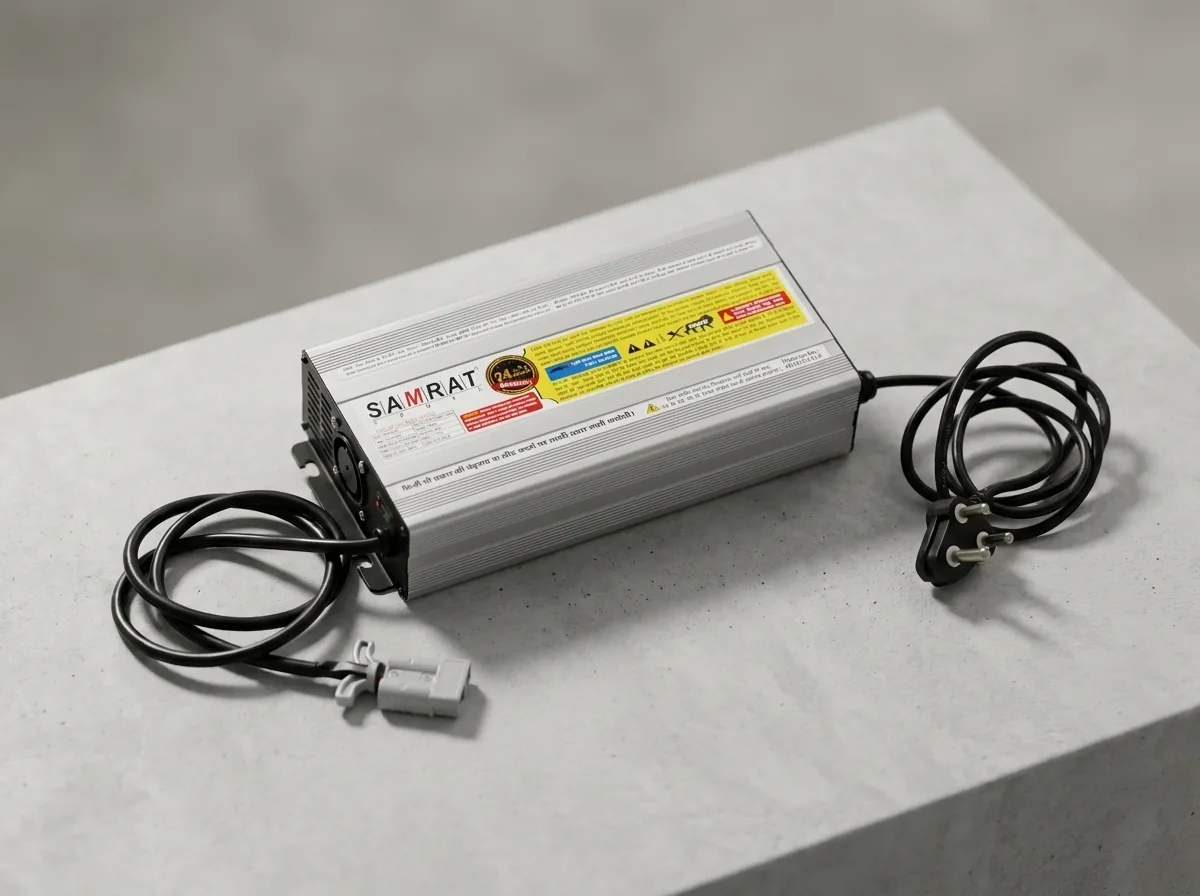
1500 Volt EV Charger
High-output aluminium-bodied charger for e-rickshaw and e-cart packs, with spark and overcharge protection. Built and tested in New Delhi.
₹6,300 incl. GST · 24-month warranty
Why any of this matters
You do not need to understand power electronics to buy a charger. But the stages above are exactly where cost gets removed from a cheap one: the EMI filter disappears, PFC was never there, the isolation barrier is marginal, the capacitor is underrated, the thermal design assumes 25 °C, and the control is a comparator rather than a controller.
None of that is visible from outside, and none of it stops the charger working on day one. It shows up in year two, as a charger that has become slow, or a battery that has quietly been mistreated for eighteen months.